To a layperson, the features, components, and design considerations of manufactured goods are often insignificant. A technologically literate person will analyze a product, see its face value, and understand how and why it was manufactured.
Just as the infamous industrial designer, Charles Eames, once said, “eventually everything connects.”
Engineers, designers, and manufacturing technicians are consistently making decisions that solve our evolving technological world’s problems. How do manufacturing experts make these decisions, and what are the reasons for their choices? An area of manufacturing that may be of interest to examine is the subset of sheet metal forming and fabrication.
Sheet Metal Overview
To fully understand the design intent of sheet metal components in the manufacturing industry, it is essential to study the types of sheet metal, their characteristics, and their components. Sheet metal is commonly defined as stock material between 0.006″ to 0.250″ in thickness. Although thickness may vary, material thinner than a sheet is typically considered foil, and material thicker than a sheet is called a plate.
When referring to sheet metal thickness, it is common to use the gauge number assigned to a specific sheet. The sheet metal gauge is a given number based on comparing the thickness dimension to its weight per square foot. These gauges typically range from 3 to 38 depending on the type of material of the sheet stock. Ferrous and nonferrous metals will then logically have different gauges. A lower gauge number indicates a thicker piece of material, and a higher gauge number indicates a thinner material.
The production process of sheet metal consists of the following:

● Stages
● Melting
● Pouring
● Pickling
● Rolling
● Annealing
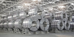
The end product is delivered to the customer from the mill in rolls or is processed further into dimensional sheets.
Sheet metal parts can be made from several metal types, including stainless steel, cold-rolled steel, galvanized steel, aluminum, copper, and brass. A fundamental aspect of the design of sheet metal components is understanding the characteristics of the materials above. Standard stainless steel selections for sheet metal parts include grades 316, 304, 410, and 430. While the 300 series of stainless steel offers high corrosion resistance levels, the 400 series of stainless offers lower expense and higher heat treatability levels.
When considering aluminum for sheet metal components; grades 1100, 3003, 5052, and 6061 are reliable due to their strength, formability, weldability, and corrosion resistance.
It’s recommended to choose a cold-rolled 1008 or 1018 if the need for steel sheet metal exists. Cold rolled steel is of higher quality when compared to its counterpart hot rolled steel. Cold rolled steel will have a tighter thickness tolerance and a descaled surface for better surface finishes.
As with most production materials, sheet metal components are utilized in industries that span from the medical and aerospace fields to kitchen appliances. The medical field requires sheet metal parts for stainless steel storage cabinets, medical imaging equipment, and pharmaceutical supplies. Perhaps the most well-known industry that uses sheet metal parts is the aerospace industry. Components, including aircraft wing ribs, aircraft bulkheads, and jet engine exhaust systems, comprise sheet metal assemblies.
Sheet Metal Manufacturing Processes
One of the challenges of designing sheet metal components is devising the optimal manufacturing process to yield the highest quality part in a competitive amount of time. Knowing the vast possibilities of sheet metal manufacturing starts with understanding the following manufacturing processes. Separating, forming, and combining are three manufacturing processes that change production materials’ form and function. A wide variety of methods accomplishes each of these categories of manufacturing processes.
The separating process is divided into shearing and chip removal methods. Shearing methods cut material from the stock with no material loss. Such tools include:
● Shears
● Punches
● Dies
Chip removal methods cut material away from the stock with a loss of material. A cutting tool is fed
into, along, or through the material, creating a chip, and leaving a kerf. Chip removal methods include:
● Saws
● Mills
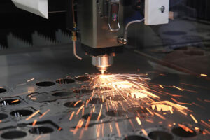
● Lasers
● Waterjet cutters
● Abrasives
The forming process is divided into bending, compressing, and stretching methods. Tools that perform these methods include:
● Brakes
● Hammers
● Presses
● Rollers
● Drawing machines
Combining processes are carried out by bonding, coating, and mechanical fastening methods. Adhesive and cohesive bonds accomplish the bonding method. Adhesive bonds join two components using structural acrylics, epoxies, and films, whereas cohesive bonds are commonly achieved by welding in the sheet metal industry. Mechanical fastening methods are split into two categories of threaded and non-threaded fasteners. Threaded fasteners include bolts and screws, while non-threaded fasteners are made of rivets and pins.
As mentioned above, riveting is a staple process in the fastening of sheet metal parts. Contained in the list below are considerations for designing parts that will ultimately require rivets.
● Aerospace rivet terminology includes the manufacturer’s head, shank, and shop head.
● Aerospace rivets have several heads, including flathead, brazier head, countersunk head, and universal head.
● Use the rivet manufacturers recommended drill bit size for pre-drilling
● The resultant shop head should be 1-½ times larger in diameter than the shank of the rivet and ½ of the shank diameter in thickness.
● The distance from the edge of the sheet metal to the rivet is called edge distance and should be no less than two times larger than the rivet shank diameter.
● Rivet to rivet distance in rows is called pitch and should be no less than three times the rivet shank diameter.
● Rivet to rivet distance in columns is called gauge and should be roughly 75% of the pitch.
Design for Manufacturability Considerations
All too often, sheet metal components spend more time than necessary going through revisions and change orders. Several design considerations may improve the outcome. The following is a list of some of these considerations to design sheet metal parts for manufacturability.
● Including bend relief will decrease the chances of the metal tearing went bent.
● Flanges should be formed perpendicular to the grain structure of the metal to avoid tearing.
● Assigning tolerances tighter than necessary will increase the part’s cost and cause premature wearing of punches and dies.
● Coining, collars and chamfers added to corners and holes will increase the stability of the finished part.
● Simplifying multi-piece assemblies by combining parts with similar roles will reduce product costs due to reduced production time.

● Using standard tooling will increase the manufacturability of the part.
● Ensuring part assembly from one side will increase the ease of assembly of a sheet metal product.
● Deburr all edges and sharp corners.
● Remove all heat-affected zones following laser cutting.
● When at all possible, leave the decision of the welding method up to the manufacturer.
Designing Sheet Metal Parts Wrap-up
Any manufacturing effort’s end goal is to provide the consumer with the best product possible at the most affordable price point. Technical knowledge and hands-on experience with the materials, tools, and sheet metal fabrication processes are essential to providing the consumer with the best product and the manufacturer. Keeping in mind the above considerations will result in a sheet metal component that is of high quality and should provide assistance to the end-product manufacturer.
