A discussion of the manufacturing industry is never complete without mentioning Henry Ford and his assembly line. Henry Ford had once said, “Any customer can have a car painted any color that he wants, so long as it is black.” One driving factor behind the ability of the Ford Motor Company to produce an affordable vehicle for the masses at that time was their pursuit of simplicity and standardization.
As processes, materials, tools, and parts are standardized or simplified in a manufacturing environment, a finished product’s total production time will decrease. In the modern era of manufacturing, the need for, and execution of, instant access to information, data, and precision parts is vastly different from Henry Ford’s time. Although this may be true, the benefits of planning the design of a product around its manufacturing processes is an age-old practice that is still valid to this day.
Most products in the manufacturing industry can be linked, in some way, to a machining operation. Whether a product requires machined parts to complete its’ assembly, or it requires precision machined tooling for subassembly fabrication, machining operations are often the core of product development and manufacturing. With the spotlight on machining, what are the essential items to consider when designing a part for manufacturability? How does a machined part go from concept to reality? The following information should assist in the effort to achieve a manufacturable product.
Machining Processes
One of the first things to consider when designing a machined part for manufacture is to assess what manufacturing processes need to occur and in what order.
● Saw cutting – Completed using vertical or horizontal bandsaws, typically used as an initial operation to bring bar and round stock to size for further machining operations. When batches of parts must be saw cut, material stops should provide repeatability of the saw cut length. When selecting tolerances, it is important to note that a unilateral tolerance should be assigned to ensure enough material is present for the proceeding machining operations (ex. 3.00 + .03/-0).

● Milling – A machining process utilizing a multi-axis machine tool with a rotary cutting bit to remove material from the saw cut stock subtractively. Traditional manually operated milling machines come in vertical or horizontal spindle orientations; and include three-axis movement (X, Y, Z).
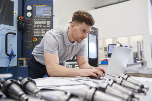
Accommodating for the world of complex shape machined parts is readily achieved using a CNC (Computer Numerical Control) milling center. These automated machine tools exponentially increase the capability of more complex and precision parts to be manufactured.
The simultaneous and positional capabilities of 5-axis CNC machine tools are currently rising in popularity due to reduced setup time compared to more traditional 3-axis work.
Horizontal CNC milling machines offer excellent chip evacuation that directly results from the part’s orientation and the spindle inside the enclosure. Increasing chip evacuation will improve surface finishes and tool life.
● Turning – A machining process utilizing a multi-axis machine with a non-rotating cutting tool that removes material from rotating round stock. Traditional manually operated lathes move in two axes.
CNC turning centers offer increased automation as compared to their traditional manual predecessors. CNC lathes will often feature live tooling options that allow milling operations to occur in one machine tool.
The use of sub spindles in a CNC lathe can provide an automated solution to second operation setups.
CNC lathes may also have bar feeders that can provide “lights out” machining for increased part throughput.
● Additional Machining Processes – Surface grinders and EDM (Electrical Discharge Machining) are other machine tools that are proven capable of tight tolerances. These machine tools are most prevalent in the tool and die industry and found in most capable machine shops.
Material Considerations
Choosing the right material for a machined part may seem to be a daunting task, but the following materials are
good starting points to narrow your search:

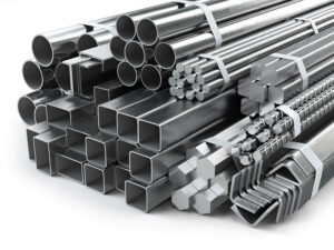
● 6061, 7075 Aluminum – Great machinability, lightweight, available in various sizes and shapes, and corrosion-resistant.
● 1018 Steel – Inexpensive, increased machinability as compared to other carbon steel grades, and excellent weldability.
● 304, 316 Stainless Steel – Corrosion resistant, increased machinability as compared to other stainless steels, and weldability,
● Delrin – Great machinability, moisture and chemical resistant, low coefficient of friction.
There are plenty of other materials to select from, including brass, bronze, Inconel, nylon, ABS, and UHMW. The process of choosing the right material for a machined part should begin with assessing the end product’s needs and a clear line of communication between the client, engineer, and machinist.
Machined Part Feature Considerations
The real work in designing a machined part for ease of manufacture lies within the decisions made when designing the part’s features. A design is only a concept unless it can be machined. All too often, conceptual 3D models include features that are not possible or not feasible to be machined. The following list contains some of the general design considerations regarding the features of a machined part:
● Design holes to use industry-recognized drill bit sizes.

● Hole depth should be less than 4 or 5 times the diameter of the drill.
● Holes should not be placed on angles. Drilling a hole on an angled surface will result in the drill bit walking.
● Design pocket radii to accommodate standard end mills (ex. .25” internal radius for a .5” dia end mill).
● Avoid sharp internal corners.
● If sharp internal corners are necessary, they can be created with an EDM or by drilling “mickey mouse corners.”
● Choose chamfers as an external edge break as compared to a fillet.
● Design internal threads to include a relief at the bottom of the hole for tap and chip clearance.
● Avoid deep-pocket features—a depth of the pocket four times larger than its width.
● Design parts to fit within standard stock material sizes.
● Avoid tight tolerances when they are not crucial to the function of the end product.
Fixturing
Although the design considerations that go into the machined part features are among the most important, the most overlooked aspect of designing parts for ease of manufacture is how they will hold while being machined. Any part can be designed, but the real question is, can it be made?
The answer to the question above comes from what is known as a fixture. A fixture in machining is simply a device that will hold onto the stock material as it is machined. Various simple and complex methods can accomplish this, but it is imperative to keep in mind how the part will be fixtured inside the machine when designing the finished part.
When planning and designing the fixture for a part, it is crucial to reduce the number of different setups or operations it takes to machine a single part. The more a part needs relocating inside the machine, the greater the time it takes to make that part, the greater the risk will be for inaccuracies, and ultimately the higher the final cost of the product will be.
CAD/CAM Considerations
For technically minded people, part of the beauty of living in the 21st century is the efficiency of designing a product and bringing that product to life. In part, this is due to the instant access to CAD software (computer-aided design) that is currently available.
Whether you are an engineer, a machinist, or a hobbyist, there is a CAD program that suits your work’s needs. The industry standard choices in CAD and CAM (Computer-Aided Manufacturing) software are typically Mastercam and Solidworks. Software packages such as Autodesk Fusion 360 are gaining momentum due to their low cost and versatility, allowing the end-user to see a part go from idea through manufacture all within one program.

Final Thoughts
There are many more factors to consider when designing a part that will be machined. Although this may be true, if the considerations mentioned are adhered to, the part’s manufacturability will undoubtedly increase. If you are an engineer, an industrial designer, a machinist, or a hobbyist, make an effort to standardize the tools, materials, and processes you use to bring a product to market. This effort will payback in the form of reduced production time, reduced model revisions, and in the end, increased revenue.
